XT SERIES GATE VALVES
The Valveworks USA XT Series gate valves are engineered for Enhanced Oil Recovery (EOR) applications, including Steam Assisted Gravity Drainage (SAGD), where elevated temperature performance is essential. These high-performance valves are designed to operate in extreme conditions, withstanding temperatures up to 650°F (345°C).
Built with industry-leading sealing technology and proven durability, the XT Series offers multiple configurations based on application needs, supporting wellbore and flowline pressures ranging from 0 to 15,000 PSI. These full-bore valves minimize turbulence and allow downhole tools to pass through easily, ensuring optimal flow performance.
Designed with a high percentage of parts interchangeability across models, the XT Series simplifies maintenance and enhances lifecycle value. Whether in high-viscosity oil fields or extreme thermal environments, these valves deliver long-term reliability and performance.
This document provides an in-depth breakdown of Valveworks USA XT Series gate valves, highlighting key features, temperature ratings, dimensional and technical specifications, and material classifications— empowering you to choose the ideal gate valve for your demanding applications.
PDF BrochureExplore the Valveworks USA XT Series Gate Valves, including models XT1DS, XT1SG, XT1RC DS, XT1RC SG, and XT2. These unidirectional and bidirectional gate valves are engineered with slab and expanding gate options, available in forged or cast bodies. Ideal for high-pressure and oilfield applications, this chart helps you compare key features side-by-side for better selection.
Unidirectional, Expanding Gate, Cast Body
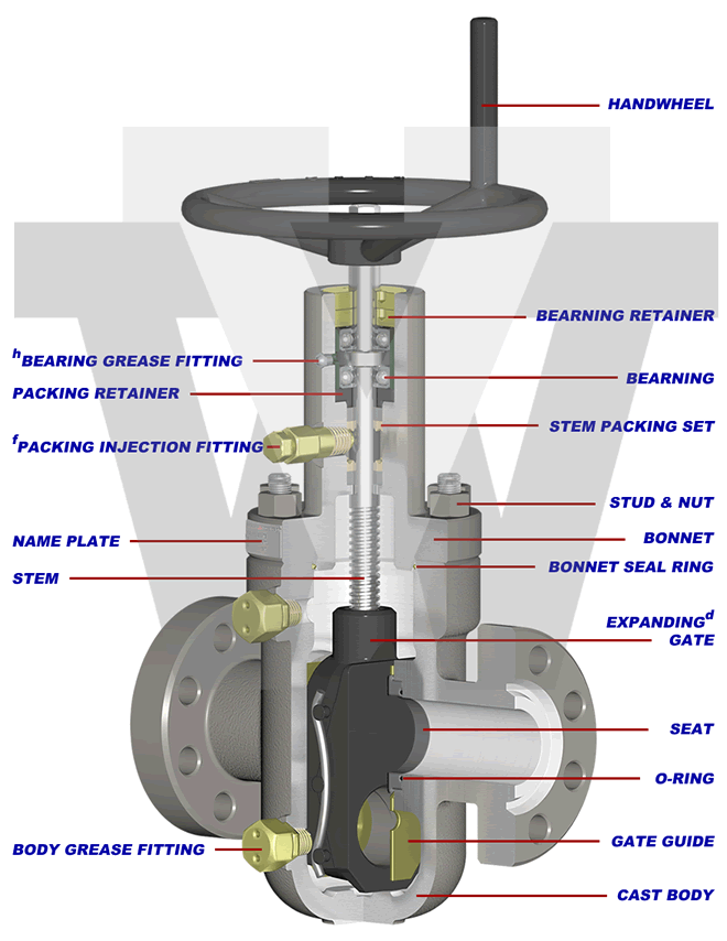
d) See engineering note titled “Expanding Gate Assembly Operation Explained” for details.
f) Stuffing box can be repacked via injectable packing while the valve is in service up to the rated working pressure.
h) Valve bonnet equipped with grease port(s) and fitting(s) for bearing lubrication.
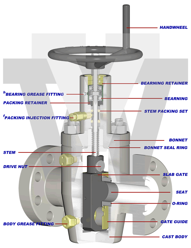
Bidirectional, Slab Gate, Cast Body
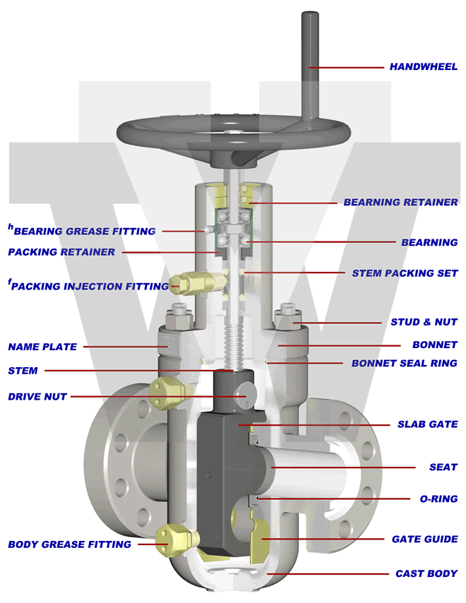
h) Valve bonnet equipped with grease port(s) and fitting(s) for bearing lubrication.
Unidirectional, Expanding Gate, Forged Body
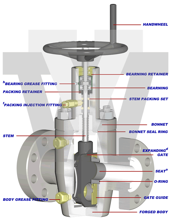
d) See engineering note titled “Expanding Gate Assembly Operation Explained” for details.
f) Stuffing box can be repacked via injectable packing while the valve is in service up to the rated working pressure.
h) Valve bonnet equipped with grease port(s) and fitting(s) for bearing lubrication.
Bidirectional, Slab Gate, Forged Body
h) Valve bonnet equipped with grease port(s) and fitting(s) for bearing lubrication.
Bidirectional, Slab Gate, Forged Body
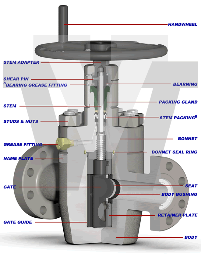
h) Valve bonnet equipped with grease port and fitting for bearing lubrication.
DISCLAIMER: THE ACTUAL PRODUCT MAY VARY SLIGHTLY FROM SHOWN SCHEMATIC DUE TO ENGINEERING APPROVED VARIATION.
WARNING: L7M / B7M STUDS CANNOT BE SUBSTITUED FOR L7 / B7 STUDS.
PRODUCT FEATURES
This comparison chart outlines all technical specifications, pressure ratings, sealing mechanisms, bore sizes, material classes, and design characteristics across the full XT Series of Valveworks USA gate valves. This includes models XT1DS, XT1SG, XT1RC DS, XT1RC SG, and XT2. Designed for high-temperature, high-pressure oilfield applications, these valves offer both expanding and slab gate options in cast or forged bodies.
| FEATURES | XT1DS | XT1SG | XT1RC DS | XT1RC SG | XT2 |
|---|---|---|---|---|---|
| Flow Direction | Unidirectionala | Bidirectional | Unidirectionala | Bidirectional | Bidirectional |
| Available Bore Size & Rated Working Pressure (PSI)b | 2-1/16" 2K,3K,5K 2-9/16" 2K,3K,5K 3-1/8" 2K,3K,5K 4-1/16" 2K,3K,5K 5-1/8" 2K,3K,5K |
2-1/16" 2K,3K,5K 2-9/16" 2K,3K,5K 3-1/8" 2K,3K,5K 4-1/16" 2K,3K,5K 5-1/8" 2K,3K,5K |
2-1/16" 2K,3K,5K 2-9/16" 2K,3K,5K 3-1/8" 2K,3K,5K 4-1/16" 2K,3K,5K 5-1/8" 2K,3K,5K |
2-1/16" 2K,3K,5K 2-9/16" 2K,3K,5K 3-1/8" 2K,3K,5K 4-1/16" 2K,3K,5K 5-1/8" 2K,3K,5K |
1-13/16" 10K,15K 2-1/16" 5K,10K,15K 2-9/16" 5K,10K,15K 3-1/8" 3K,5K 3-1/16" 10K,15K 4-1/16" 3K,5K,10K |
| Available PSLc | 1,2 | 1,2 | 1,2,3,3G,4 | 1,2,3,3G,4 | 1,2,3,3G,4 |
| Available PR | 1,2,2F | 1,2,2F | 1,2,2F | 1,2,2F | 1,2,2F |
| Material Classes | AA,BB,CC,DD,EE,FF | AA,BB,CC,DD,EE,FF | AA,BB,CC,DD,EE,FF,HH | AA,BB,CC,DD,EE,FF,HH | AA,BB,CC,DD,EE,FF,HH |
| Valve Body | Cast | Cast | Forged | Forged | Forged |
| Gate Type | Expandingd | Slab | Expandingd | Slab | Slab |
| Sealing Action | Mechanical | Pressure-Energized | Mechanical | Pressure-Energized | Pressure-Energized |
| Operation Type | Manuale | Manuale | Manuale | Manuale | Manuale |
| Bore Type | Full-Bore | Full-Bore | Full-Bore | Full-Bore | Full-Bore |
| Gate/Seat Seal | Metal to Metal | Metal to Metal | Metal to Metal | Metal to Metal | Metal to Metal |
| Stem Type | Non-rising | Non-rising | Non-rising | Non-rising | Non-rising |
| Stem Packing Type | Grafoil®-V | Grafoil®-V | Grafoil®-V | Grafoil®-V | Spring-Energized |
| Repacking | Yesf | Yesf | Yesf | Yesf | Yesg |
| Thrust Bearings | 2 | 2 | 2 | 2 | 2 |
| Body Lubrication Fittings | 2h | 2h | 2h | 2h | 1 |
| Body/Bonnet Connection | Bolted | Bolted | Bolted | Bolted | Bolted |
| End Connections | Flanged (RTJ) | Flanged (RTJ) | Flanged (RTJ) | Flanged (RTJ) | Flanged (RTJ) |
| Temperature Range | -50°F to 650°F | -50°F to 650°F | -50°F to 650°F | -50°F to 650°F | -20°F to 350°F |
a. Equipped with a non-sealing seat on the upstream side. See engineering note titled “Model XT1DS & Model XT1RC DS” for details.
b. 2 1/16″ x 1 13/16″, 3 1/8″ x 3 3/16″, 4 1/16″ x 4 1/8″, and 4 1/16″ x 4 1/4″ available upon request.
c. Product Specification Level
d. See engineering note titled “Expanding Gate Assembly Operation Explained” for details.
e. Also referred to as “HANDWHEEL OPERATED”
f. Stuffing box can be repacked via injectable packing while the valve is in service up to the rated working pressure.
g. Stuffing box can be repacked via back seat while the valve is in service up to the rated working pressure.
h. Valve bonnet equipped with grease port(s) and fitting(s) for bearing lubrication.
ENGINEERING NOTES
Expanding Gate Assembly Operation Explained – The expanding gate assembly consists of two main components: the gate (major) and the segment (minor). These components are assembled together using precision machined pins and high-quality, precision formed and treated Nickel-Chromium alloy springs. When the valve is manually operated, the gate and segment act one against the other by means of a dual expanding wedge when the valve is either fully opened or fully closed. This expansion effect of the gate assembly against the valve seats, through parallel faces of the gate assembly, provides a strong and positive seal against pulsations and vibrations created by flow conditions. This is advantageous when attempting to accomplish a positive seal in both high and low pressure conditions.
Model XT1DS & Model XT1RC DS – These models are unidirectional gate valves equipped with an expanding gate assembly and a sealing seat in the downstream seat pocket. The upstream seat pocket is equipped with a non-sealing seat assembly. This allows pressure to bypass the upstream seat, equalize throughout the valve body, and only seal against the downstream seat assembly as the original Model M was intended. All model XT1DS valves are marked with a flow direction arrow for accurate installation.
NOTE: When bidirectional operation is required, a slab gate valve is necessary. XT1 Series expanding gate valves (Model XT1DS and Model XT1RC DS) are not designed for bidirectional operation.
Pressure Testing – XT1 series gate valves are not intended to be tested through the body lubrication fittings. These fittings are designed for lubrication purposes only. Shell tests and gate/seat tests shall be conducted from the end/outlet connection by qualified personnel only.
TEMPERATURE RATING
This table displays the temperature classifications used in Valveworks USA XT Series valves. Each classification, including L, P, X, and Y, defines a specific operating temperature range designed for high-performance oilfield environments.
| CLASSIFICATION | OPERATING TEMP. RANGE |
|---|---|
| L | -50°F (-46°C) TO 180°F (82°C) |
| P | -20°F (-29°C) TO 180°F (82°C) |
| X | 0°F (-18°C) TO 350°F (180°C) |
| Y | 0°F (-18°C) TO 650°F (345°C) |
TABLE 3 – MATERIAL REQUIREMENTS
The following table details the API 6A material class requirements for Valveworks USA gate valves, specifying the minimum material composition for body, bonnet, end connections, outlet connections, pressure-controlling parts, and stems. This classification ensures compliance with high-pressure industrial and oilfield standards.
| Material Class | Service Type | Minimum Material Requirements | |
|---|---|---|---|
| Body, Bonnet, End & Outlet Connections | Pressure-Controlling Parts & Stems | ||
| AA | General Service | Carbon or Low-Alloy Steel | Carbon or Low-Alloy Steel |
| BB | General Service | Carbon or Low-Alloy Steel | Stainless Steel |
| CC | General Service | Stainless Steel | Stainless Steel |
| DD | Sour Servicea | Carbon or Low-Alloy Steelb | Carbon or Low-Alloy Steelb |
| EE | Sour Servicea | Carbon or Low-Alloy Steelb | Stainless Steelb |
| FF | Sour Servicea | Stainless Steelb | Stainless Steelb |
| HH | Sour Servicea | Corrosion-Resistant Alloy (CRA)acd | Corrosion-Resistant Alloy (CRA)acd |
VALVEWORKS USA GATE VALVE MODEL EXPLANATION

FLANGED GATE VALVES
This XT Series Gate Valve dimension table from Valveworks USA includes full specifications for all valve sizes (2 1/16" to 5 1/8") across 2K, 3K, and 5K pressure ratings. It details face-to-face dimensions, bore sizes, centerline heights, ring joint numbers, stud sizes, weights, torque values, and more — making it a critical reference for oilfield and high-temperature applications.
| SIZE | WP (PSI) | A | B | C | D | E | NT | RJ | BSS | N | WT (LBS) | HT (FT-LBS) |
|---|---|---|---|---|---|---|---|---|---|---|---|---|
| 2 1/16 | 2K | 11 5/8 | 2 1/16 | 5 1/4 | 19 1/2 | 10 | 14 | R-23 | 5/8 | 8 | 120 | 32 |
| 3K | 14 5/8 | 2 1/16 | 5 1/2 | 19 5/8 | 13 | 14 | R-24 | 7/8 | 8 | 180 | 40 | |
| 5K | 14 5/8 | 2 1/16 | 5 1/2 | 19 5/8 | 13 | 14 | R-24 | 7/8 | 8 | 180 | 57 | |
| 2 9/16 | 2K | 13 1/8 | 2 9/16 | 6 3/8 | 20 1/2 | 13 | 16 1/2 | R-26 | 5/8 | 8 | 180 | 37 |
| 3K | 16 5/8 | 2 9/16 | 6 5/8 | 20 7/8 | 16 | 16 1/2 | R-27 | 7/8 | 8 | 220 | 49 | |
| 5K | 16 5/8 | 2 9/16 | 6 5/8 | 20 7/8 | 16 | 16 1/2 | R-27 | 7/8 | 8 | 220 | 66 | |
| 3 1/8 | 2K | 14 1/8 | 3 1/8 | 7 5/8 | 22 7/8 | 13 | 20 3/4 | R-31 | 7/8 | 8 | 220 | 48 |
| 3K | 17 1/8 | 3 1/8 | 7 5/8 | 23 | 16 | 20 3/4 | R-31 | 1 | 8 | 300 | 65 | |
| 5K | 18 5/8 | 3 1/8 | 7 5/8 | 23 | 16 | 20 3/4 | R-35 | 1 | 8 | 340 | 90 | |
| 4 1/16 | 2K | 17 1/8 | 4 1/16 | 9 5/8 | 26 1/2 | 16 | 24 3/4 | R-37 | 1 | 8 | 360 | 81 |
| 3K | 20 1/8 | 4 1/16 | 9 5/8 | 26 5/8 | 20 | 24 3/4 | R-37 | 1 3/8 | 8 | 520 | 67 | |
| 5K | 21 5/8 | 4 1/16 | 9 5/8 | 26 5/8 | 20 | 24 3/4 | R-39 | 1 3/8 | 8 | 560 | 130 | |
| 5 1/8 | 2K | 22 1/2 | 5 1/8 | 11 3/4 | 30 | 24 | 30 1/4 | R-41 | 1 3/8 | 8 | 770 | 150 |
| 3K | 24 1/8 | 5 1/8 | 11 3/4 | 30 | 24 | 30 1/4 | R-41 | 1 3/8 | 8 | 810 | 210 | |
| 5K | 28 5/8 | 5 1/8 | 11 3/4 | 30 | 24 | 30 1/4 | R-41 | 1 3/8 | 8 | 940 | 366 |
THREADED GATE VALVES
This table details the full dimensional specifications for Valveworks USA XT Series gate valves in 10K and 15K pressure classes. It includes sizes from 1-13/16" through 4-1/16", with measurements such as face-to-face dimensions (A), bore sizes (B), bonnet and body heights (C, D, E), ring joint types (RJ), stud sizes (BSS), weights, torque ratings, and more.
| SIZE | WP (PSI) | A | B | C | D | E | NT | RJ | BSS | N | WT (LBS) | HT (FT-LBS) |
|---|---|---|---|---|---|---|---|---|---|---|---|---|
| 1 13/16 | 10K | 18 1/4 | 1 13/16 | 5 13/16 | 18 13/16 | 16 | 11 3/4 | BX-151 | 1 1/8 | 8 | 270 | 59 |
| 15K | 18 | 1 13/16 | 6 13/16 | 18 13/16 | 16 | 11 3/4 | BX-151 | 1 1/4 | 8 | 275 | 89 | |
| 2 1/16 | 5K | 14 5/8 | 2 1/16 | 5 7/8 | 18 7/8 | 14 | 12 | R-24 | 7/8 | 8 | 189 | 32 |
| 10K | 20 1/2 | 2 1/16 | 5 13/16 | 18 13/16 | 16 | 12 1/2 | BX-152 | 1 1/8 | 8 | 275 | 66 | |
| 15K | 19 | 2 1/16 | 6 1/8 | 18 13/16 | 16 | 12 1/2 | BX-152 | 1 1/4 | 8 | 350 | 103 | |
| 2 9/16 | 5K | 16 5/8 | 2 9/16 | 6 5/16 | 19 1/2 | 16 | 16 1/4 | R-27 | 1 | 8 | 275 | 49 |
| 10K | 22 1/4 | 2 9/16 | 6 7/8 | 19 5/8 | 20 | 16 | BX-153 | 1 1/4 | 8 | 485 | 111 | |
| 15K | 21 | 2 9/16 | 7 13/16 | 22 7/8 | 20 | 15 1/2 | BX-153 | 1 1/8 | 12 | 520 | 221 | |
| 3 1/8 | 3K | 17 1/8 | 3 1/8 | 7 13/16 | 20 1/2 | 16 | 17 1/2 | R-31 | 1 1/8 | 8 | 337 | 40 |
| 5K | 18 5/8 | 3 1/8 | 7 9/16 | 20 1/2 | 16 | 17 1/2 | R-35 | 1 1/8 | 8 | 355 | 67 | |
| 3 1/16 | 10K | 24 3/8 | 3 1/16 | 8 1/8 | 22 | 23 | 17 1/2 | BX-154 | 1 3/8 | 8 | 550 | 140 |
| 15K | 23 9/16 | 3 1/16 | 9 1/8 | 25 5/8 | 23 | 15 1/2 | BX-154 | 1 3/8 | 12 | 914 | 308 | |
| 4 1/16 | 3K | 20 1/8 | 4 1/16 | 9 5/16 | 22 | 20 | 24 1/4 | R-37 | 1 1/4 | 8 | 498 | 70 |
| 5K | 21 5/8 | 4 1/16 | 9 13/16 | 22 | 20 | 23 1/4 | R-39 | 1 1/4 | 8 | 550 | 113 | |
| 10K | 26 3/8 | 4 1/16 | 10 1/8 | 28 3/4 | 24 | 23 1/4 | BX-155 | 1 5/8 | 8 | 950 | 258 |
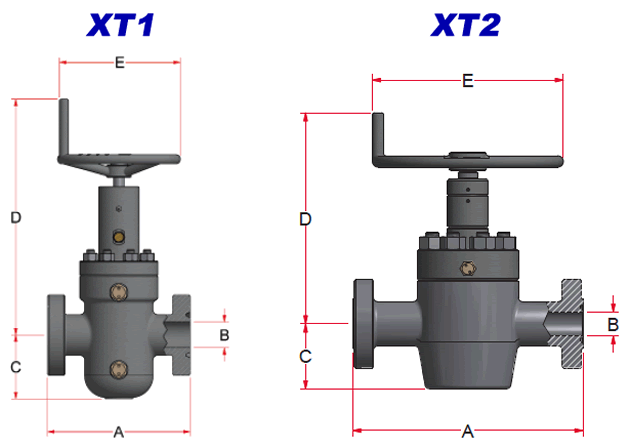
DIMENSION TABLE KEY
This reference table explains the dimensional key terms used throughout the Valveworks USA XT Series gate valve specifications. It includes abbreviations for face-to-face dimensions, bore sizes, centerline heights, handwheel measurements, number of turns, ring joint types, stud sizes, and torque requirements.
| Key | Description |
|---|---|
| A | Face to Face |
| B | Valve Bore Size (Nominal) |
| C | Bore Centerline to Bottom |
| D | Bore Centerline to Top |
| E | Handwheel Diameter |
| NT | Number of Turns |
| RJ | Ring Joint |
| TS | Thread Size |
| BBS | Bonnet Stud Size |
| N | Number of Studs |
| WT | Approximate Weight |
| HT | Handwheel Operating Torque |
ABBREVIATION KEY
- MSG = Model M Slab Gate
- MDS = Model M Unidirectional
- MRC SG = Model M Round Cavity Slab Gate
- MRC DS = Model M Round Cavity Unidirectional
- HWO = Handwheel Operated (manual)
- EXP = Expanding
- SG = Slab Gate
- FE = Flanged End
- RTJ = Ring Type Joint
- PSL = Product Specification Level
- PR = Performance Requirement
- LP = Line Pipe
- STC = Casing Short Thead
- LC = Casing Long Thead
- EU = Tubing, Ecternal Upset
- CRA = Corrosion-resistant Alloy
- XYL = Xylan®
- HF = Hardfaced