M SERIES GATE VALVES
The Valveworks USA M Series gate valves provide multiple configurations engineered for wellhead, flowline, and high-pressure applications with ratings from 0 to 5,000 PSI. These precision-engineered valves offer reliable performance in extreme conditions, ensuring optimal sealing integrity.
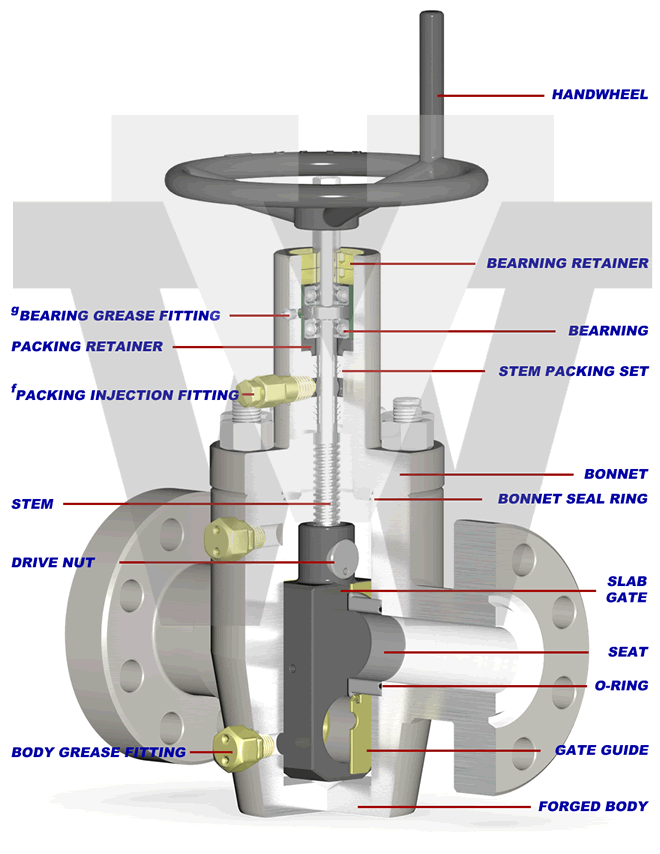
M Series gate valves are full-bore, through-conduit, high-pressure valves designed for oilfield and industrial applications. Their streamlined flow path allows downhole tools to pass through the wellhead while reducing turbulence, enhancing operational efficiency.
Designed with high interchangeability across models, the M Series minimizes maintenance time and maximizes operational efficiency. This efficiency-driven advantage supports long-term durability and optimal lifecycle management.
Below is a detailed breakdown of the Valveworks USA M Series gate valves, highlighting key features, benefits, dimensional and technical specifications, material classifications, and pressure ratings. This guide ensures you select the optimal gate valve for your specific operational needs.
PDF BrochureThe interactive tabbed chart below provides a detailed comparison of Valveworks USA M Series Gate Valves, including Model MDS, Model MSG, Model MRC DS, and Model MRC SG. These industrial gate valves are designed for wellhead and high-pressure applications, offering both unidirectional and bidirectional flow control. The visualization allows for a side-by-side comparison of key features, ensuring the selection of the best valve for operational needs.
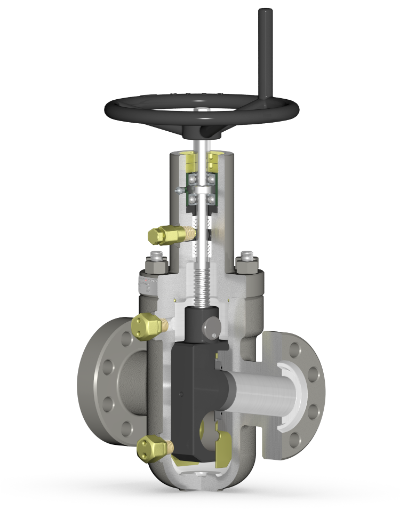
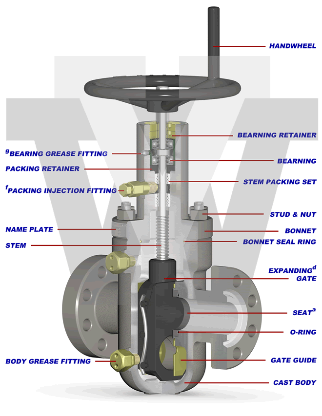
Unidirectional, Expanding Gate, Cast Body
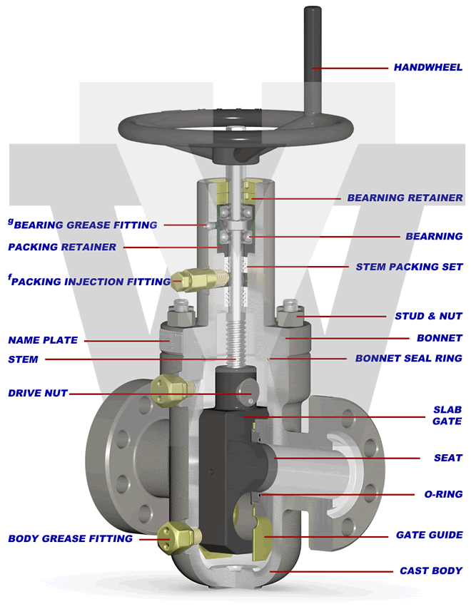
Bidirectional, Slab Gate, Cast Body
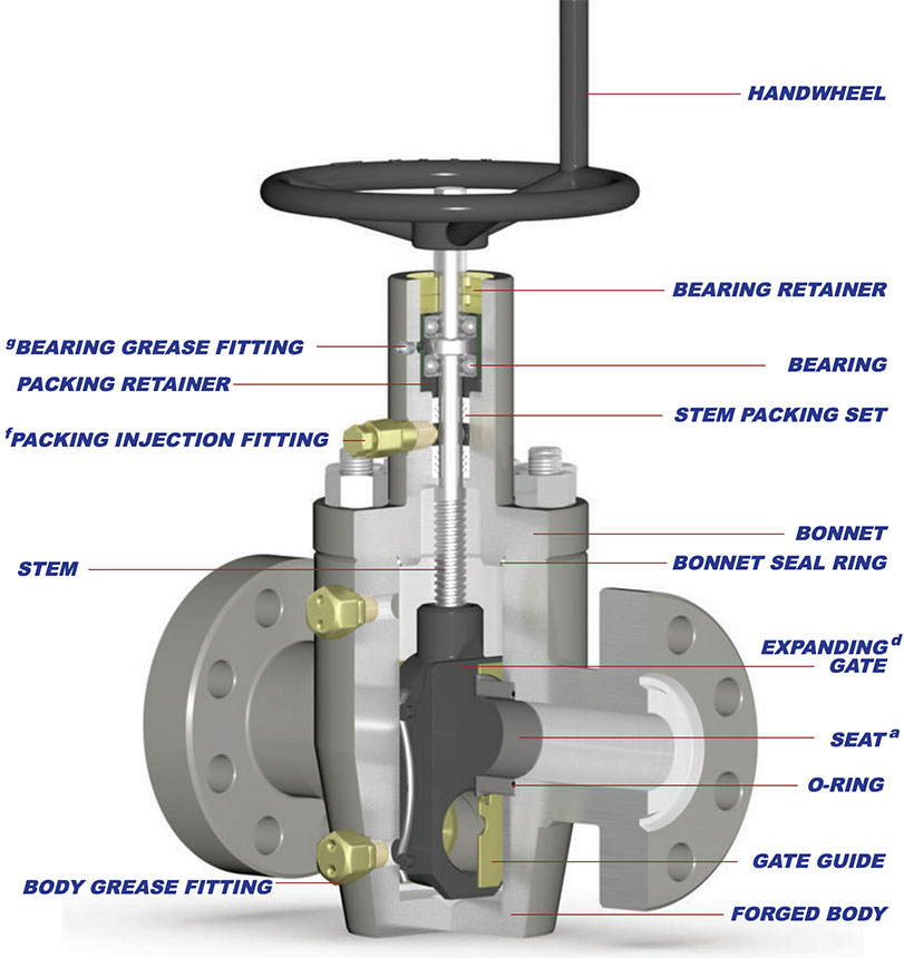
Unidirectional, Expanding Gate, Forged Body
Bidirectional, Slab Gate, Forged Body
PRODUCT FEATURES
This table provides a detailed comparison of Valveworks USA M Series Gate Valves, including the MDS, MSG, MRC DS, and MRC SG models. It highlights key specifications such as bidirectional and unidirectional flow, bore sizes, pressure ratings, material classifications, sealing mechanisms, and end connections. These high-performance industrial gate valves are designed for reliability in oilfield and high-pressure applications.
| Key Features | MDS | MSG | MRC DS | MRC SG |
|---|---|---|---|---|
| Flow Direction | Unidirectionala | Bidirectional | Unidirectionala | Bidirectional |
| Available Bore Size & Pressure (PSI)b | 2-1/16" 2K, 3K, 5K 2-9/16" 2K, 3K, 5K 3-1/8" 2K, 3K, 5K 4-1/16" 2K, 3K, 5K 5-1/8" 2K, 3K, 5K |
2-1/16" 2K, 3K, 5K 2-9/16" 2K, 3K, 5K 3-1/8" 2K, 3K, 5K 4-1/16" 2K, 3K, 5K 5-1/8" 2K, 3K, 5K |
2-1/16" 2K, 3K, 5K 2-9/16" 2K, 3K, 5K 3-1/8" 2K, 3K, 5K 4-1/16" 2K, 3K, 5K 5-1/8" 2K, 3K, 5K |
2-1/16" 2K, 3K, 5K 2-9/16" 2K, 3K, 5K 3-1/8" 2K, 3K, 5K 4-1/16" 2K, 3K, 5K 5-1/8" 2K, 3K, 5K |
| Available PSLc | 1,2 | 1,2 | 1,2,3,3G,4 | 1,2,3,3G,4 |
| Material Classes | AA, BB, CC, DD, EE, FF, HH | AA, BB, CC, DD, EE, FF, HH | AA, BB, CC, DD, EE, FF, HH | AA, BB, CC, DD, EE, FF, HH |
| Valve Body | Cast | Cast | Forged | Forged |
| Gate Type | Expandingd | Slab | Expandingd | Slab |
| Sealing Action | Mechanical | Pressure-Energized | Mechanical | Pressure-Energized |
| Operation Type | Manuale | Manuale | Manuale | Manuale |
| End Connections | Flanged (RTJ) or Threaded | Flanged (RTJ) or Threaded | Flanged (RTJ) or Threaded | Flanged (RTJ) or Threaded |
| Temperature Range | -75°F (-60°C) to 250°F (121°C) | -75°F (-60°C) to 250°F (121°C) | -75°F (-60°C) to 250°F (121°C) | -75°F (-60°C) to 250°F (121°C) |
a. Equipped with a non-sealing seat on the upstream side. See engineering note titled “Model MDS & Model MRC DS” for details.
b. 2 1/16″ x 1 13/16″, 3 1/8″ x 3 3/16″, 4 1/16″ x 4 1/8″, and 4 1/16″ x 4 1/4″ available upon request.
c. Product Specification Level
d. See engineering note titled “Expanding Gate Assembly Operation Explained” for details.
e. Also referred to as “HANDWHEEL OPERATED”
f. Also referred to as “FULL OPENING”.
g. Stuffing box can be repacked via injection packing
h. Valve bonnet equipped with grease port(s) and fitting(s) for bearing lubrication.
ENGINEERING NOTES
Expanding Gate Assembly Operation Explained – The expanding gate assembly consists of two main components: the gate (major) and the segment (minor). These components are assembled together using precision machined pins and high-quality precision formed and treated Nickel-Chromium alloy springs. When the valve is manually operated, the gate and segment act one against the other by means of a dual expanding wedge when the valve is either fully-opened or fully-closed. This expansion effect of the gate assembly against the valve seats through parallel faces of the gate assembly provides a strong and positive seal against pulsations and vibrations created by flow conditions.
Model MDS & Model MRC DS – These models are unidirectional gate valves equipped with an expanding gate assembly and a sealing seat in the downstream seat pocket. The upstream seat pocket is equipped with a non-sealing seat assembly. This allows pressure to bypass the upstream seat, equalize throughout the valve body, and only seal against the downstream seat assembly as the original Model M was intended. All model MDS valves are marked with a flow direction arrow for accurate installation.
NOTE: When bidirectional operation is required, a slab gate valve is necessary. M Series expanding gate valves (Model MDS and Model MRC DS) are not designed for bidirectional operation.
Pressure Testing – M series gate valves are not intended to be tested through the body lubrication fittings. These fittings are designed for lubrication purposes only. Shell tests and gate/seat tests shall be conducted from the end/outlet connection by qualified personnel.
TEMPERATURE RATING
The following table defines the temperature classifications for Valveworks USA gate valves, specifying the operating temperature ranges for each classification. These ratings ensure optimal performance in extreme cold and high-temperature industrial applications, making them ideal for oilfield and high-pressure environments.
| Temperature Classification | Operating Temperature Range (°F/°C) |
|---|---|
| K | -75°F (-60°C) to 180°F (82°C) |
| L | -50°F (-46°C) to 180°F (82°C) |
| N | -50°F (-46°C) to 140°F (60°C) |
| P | -20°F (-29°C) to 180°F (82°C) |
| S | 0°F (-18°C) to 140°F (60°C) |
| T | 0°F (-18°C) to 180°F (82°C) |
| U | 0°F (-18°C) to 250°F (121°C) |
| V | 35°F (2°C) to 250°F (121°C) |
MATERIAL REQUIREMENTS
The following table details the material class requirements for Valveworks USA gate valves, specifying the minimum material composition for body, bonnet, end connections, outlet connections, pressure-controlling parts, and stems. This classification ensures compliance with high-pressure industrial and oilfield standards.
| Material Class | Service Type | Minimum Material Requirements | |
|---|---|---|---|
| Body, Bonnet, End & Outlet Connections | Pressure-Controlling Parts & Stems | ||
| AA | General Service | Carbon or Low-Alloy Steel | Carbon or Low-Alloy Steel |
| BB | General Service | Carbon or Low-Alloy Steel | Stainless Steel |
| CC | General Service | Stainless Steel | Stainless Steel |
| DD | Sour Servicea | Carbon or Low-Alloy Steelb | Carbon or Low-Alloy Steelb |
| EE | Sour Servicea | Carbon or Low-Alloy Steelb | Stainless Steelb |
| FF | Sour Servicea | Stainless Steelb | Stainless Steelb |
| HH | Sour Servicea | Corrosion-Resistant Alloy (CRA)acd | Corrosion-Resistant Alloy (CRA)acd |
VALVEWORKS USA GATE VALVE MODEL EXPLANATION

FLANGED GATE VALVES
The following table provides complete dimensional specifications for Valveworks USA gate valves, covering working pressure (WP), height, weight, bore size, and key flange details. These specifications ensure compliance with oilfield and industrial valve standards.
| Size (in) | WP (PSI) | Dimensions (inches) | Flange Specifications | Weight (LBS) | HT (FT-LBS) | |||||||
|---|---|---|---|---|---|---|---|---|---|---|---|---|
| A | B | C | D | E | NT | RJ | BSS | N | ||||
| 2-1/16 | 2K | 11 5/8 | 2 1/16 | 5 1/4 | 19 1/2 | 10 | 14 | R-23 | 5/8 | 8 | 120 | 32 |
| 3K | 14 5/8 | 2 1/16 | 5 1/2 | 19 5/8 | 13 | 14 | R-24 | 7/8 | 8 | 180 | 40 | |
| 5K | 14 5/8 | 2 1/16 | 5 1/2 | 19 5/8 | 13 | 14 | R-24 | 7/8 | 8 | 180 | 57 | |
| 2-9/16 | 2K | 13 1/8 | 2 9/16 | 6 3/8 | 20 1/2 | 13 | 16 1/2 | R-26 | 5/8 | 8 | 180 | 37 |
| 3K | 16 5/8 | 2 9/16 | 6 5/8 | 20 7/8 | 16 | 16 1/2 | R-27 | 7/8 | 8 | 220 | 49 | |
| 5K | 16 5/8 | 2 9/16 | 6 5/8 | 20 7/8 | 16 | 16 1/2 | R-27 | 7/8 | 8 | 220 | 66 | |
| 3-1/8 | 2K | 14 1/8 | 3 1/8 | 7 5/8 | 22 7/8 | 13 | 20 3/4 | R-31 | 7/8 | 8 | 220 | 48 |
| 3K | 17 1/8 | 3 1/8 | 7 5/8 | 23 | 16 | 20 3/4 | R-31 | 1 | 8 | 300 | 65 | |
| 5K | 18 5/8 | 3 1/8 | 7 5/8 | 23 | 16 | 20 3/4 | R-35 | 1 | 8 | 340 | 90 | |
| 4-1/16 | 2K | 17 1/8 | 4 1/16 | 9 5/8 | 26 1/2 | 16 | 24 3/4 | R-37 | 1 | 8 | 360 | 81 |
| 3K | 20 1/8 | 4 1/16 | 9 5/8 | 26 5/8 | 20 | 24 3/4 | R-37 | 1 3/8 | 8 | 520 | 67 | |
| 5K | 21 5/8 | 4 1/16 | 9 5/8 | 26 5/8 | 20 | 24 3/4 | R-39 | 1 3/8 | 8 | 560 | 130 | |
| 5-1/8 | 2K | 22 1/2 | 5 1/8 | 11 3/4 | 30 | 24 | 30 1/4 | R-41 | 1 3/8 | 8 | 770 | 150 |
| 3K | 24 1/8 | 5 1/8 | 11 3/4 | 30 | 24 | 30 1/4 | R-41 | 1 3/8 | 8 | 810 | 210 | |
| 5K | 28 5/8 | 5 1/8 | 11 3/4 | 30 | 24 | 30 1/4 | R-41 | 1 3/8 | 8 | 940 | 366 | |
THREADED GATE VALVES
This table presents detailed technical specifications for Valveworks USA gate valves, including size, working pressure (PSI), key dimensions, thread specifications, and weight. These industrial-grade gate valves are engineered for high-pressure applications, ensuring durability and optimal performance in oilfield operations.
| Size | WP (PSI) | A | B | C | D | E | NT | TS | BSS | N | WT (LBS) | HT (FT-LBS) |
|---|---|---|---|---|---|---|---|---|---|---|---|---|
| 2-1/16 | 5K | 9 5/8 | 2 1/16 | 5 1/2 | 19 5/8 | 13 | 14 | 2 LP 2 3/8 EU | 7/8 | 8 | 125 | 57 |
| 2-9/16 | 3K | 10 1/4 | 2 9/16 | 6 5/8 | 20 7/8 | 16 | 16 1/2 | 2 1/2 LP | 7/8 | 8 | 160 | 49 |
| 5K | 10 1/4 | 2 9/16 | 6 5/8 | 20 7/8 | 16 | 16 1/2 | 2 7/8 EU | 7/8 | 8 | 160 | 66 | |
| 3-1/8 | 3K | 11 3/8 | 3 1/8 | 7 5/8 | 23 | 16 | 20 3/4 | 3 LP | 1 | 8 | 230 | 65 |
| 5K | 11 3/8 | 3 1/8 | 7 5/8 | 23 | 16 | 20 3/4 | 3 1/2 EU | 1 | 8 | 230 | 90 | |
| 4-1/16 | 3K | 13 | 4 1/16 | 9 5/8 | 26 5/8 | 20 | 24 3/4 | 4 LP | 1 3/8 | 8 | 420 | 67 |
| 5K | 13 | 4 1/16 | 9 5/8 | 26 5/8 | 20 | 24 3/4 | 4 1/2 EU 4 1/2 LC | 1 3/8 | 8 | 420 | 130 |
All dimensions are in inches.
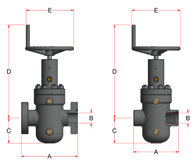
DIMENSION TABLE KEY
The following table defines key dimensional terms used in Valveworks USA gate valve specifications. Each key provides a description of its corresponding measurement or feature, ensuring clarity for engineers and professionals in high-pressure industrial applications.
| Key | Description |
|---|---|
| A | Face to Face |
| B | Valve Bore Size (Nominal) |
| C | Bore Centerline to Bottom |
| D | Bore Centerline to Top |
| E | Handwheel Diameter |
| NT | Number of Turns |
| RJ | Ring Joint |
| TS | Thread Size |
| BBS | Bonnet Stud Size |
| N | Number of Studs |
| WT | Approximate Weight |
| HT | Handwheel Operating Torque |
ABBREVIATION KEY
- MSG = Model M Slab Gate
- MDS = Model M Unidirectional
- MRC SG = Model M Round Cavity Slab Gate
- MRC DS = Model M Round Cavity Unidirectional
- HWO = Handwheel Operated (manual)
- EXP = Expanding
- SG = Slab Gate
- FE = Flanged End
- RTJ = Ring Type Joint
- PSL = Product Specification Level
- PR = Performance Requirement
- LP = Line Pipe
- STC = Casing Short Thead
- LC = Casing Long Thead
- EU = Tubing, Ecternal Upset
- CRA = Corrosion-resistant Alloy
- XYL = Xylan®
- HF = Hardfaced