FM SERIES GATE VALVES
The Valveworks USA FM Series gate valves consist of a lineup of high-performance, precision-engineered gate valves designed for oilfield and industrial applications where a 4-1/16”, 5-1/8”, or 7-1/16” bore is required.
FM Series gate valves are full-bore, through-conduit, high-pressure valves, allowing downhole tools to pass through the wellhead or Christmas tree while reducing turbulent flow. This enhances operational efficiency in oilfield production, wellhead systems, and high-pressure flowline applications.
Designed with a high percentage of parts interchangeability, the FM Series ensures efficiency in fleet management, long-term durability, and maintenance reduction. These valves are engineered to provide optimal **life cycle management integrity** while minimizing downtime for oilfield and industrial use.
This brochure provides an in-depth look at Valveworks USA FM Series Gate Valves, including key features, industry-leading benefits, performance characteristics, and technical specifications. It includes dimensional data, material classifications, and pressure ratings to help determine the optimal solution for your high-pressure applications.
PDF BrochureThe interactive tabbed chart below provides a detailed comparison of Valveworks USA FM Series Gate Valves, including Model FM1, Model FM2, Model FM3 10K, and Model FM3 15K. These high-performance industrial gate valves are engineered for extreme pressure conditions and designed for oilfield, wellhead, and high-pressure applications. The visualization allows for a side-by-side comparison of key features, ensuring the selection of the best valve for operational needs.
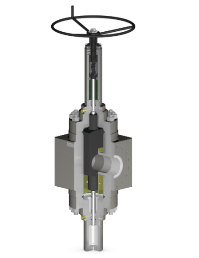
Bidirectional, Slab Gate, Studded Body
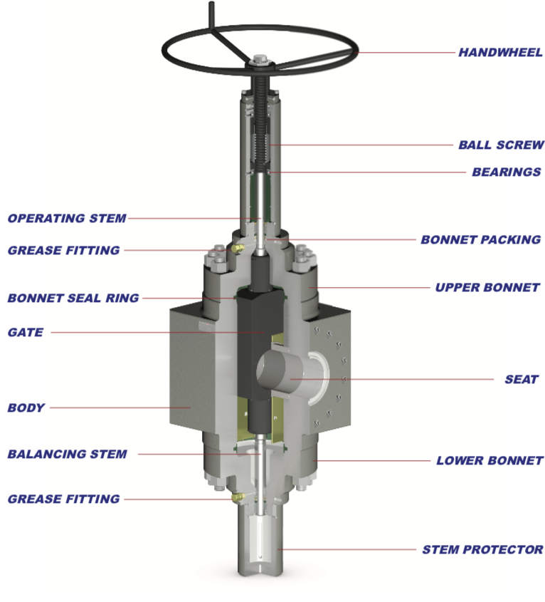
Bidirectional, Slab Gate, Flanged Body
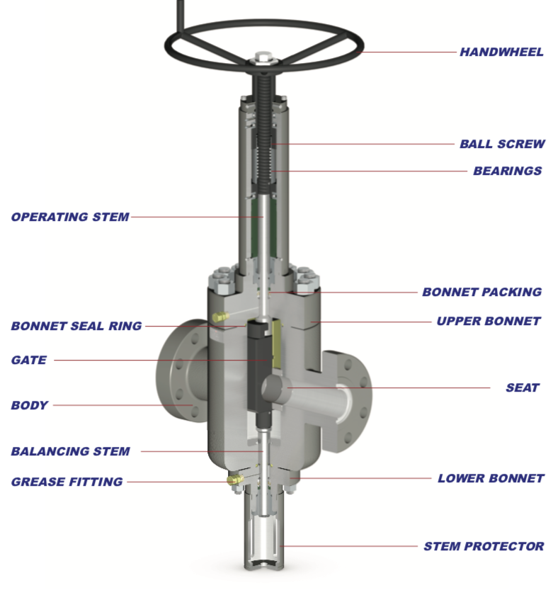
Unidirectional, Slab Gate, Flanged Body
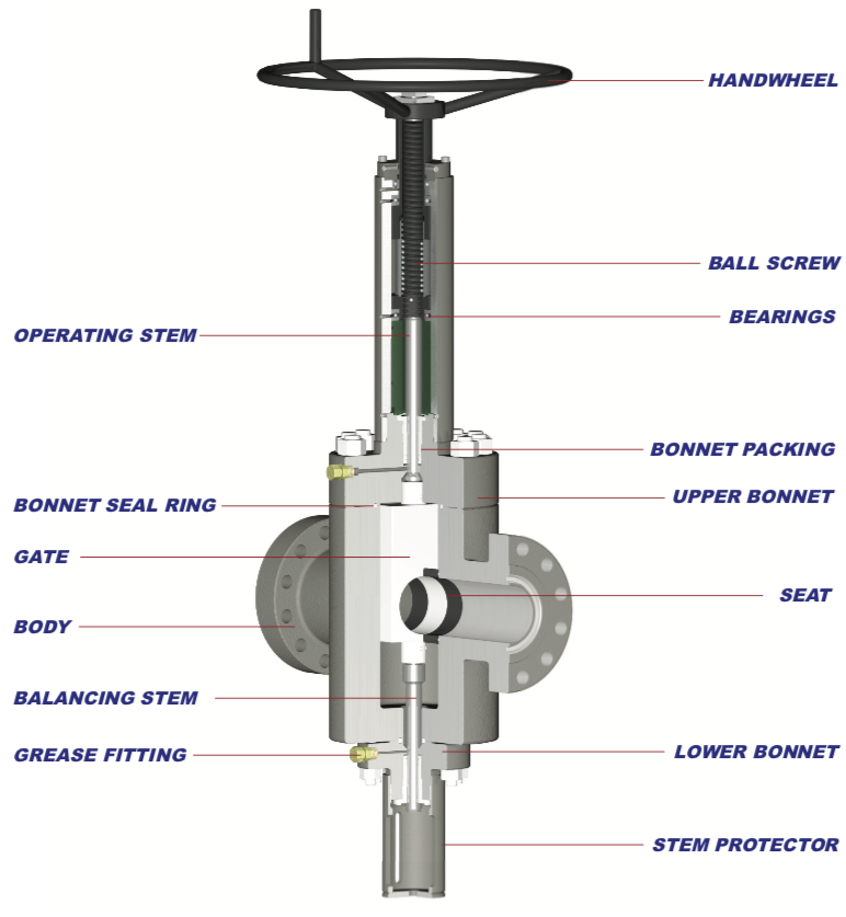
Bidirectional, Slab Gate, Flanged Body
DISCLAIMER: THE ACTUAL PRODUCT MAY VARY SLIGHTLY FROM SHOWN SCHEMATIC DUE TO ENGINEERING APPROVED VARIATION.
WARNING: L7M / B7M STUDS CANNOT BE SUBSTITUED FOR L7 / B7 STUDS
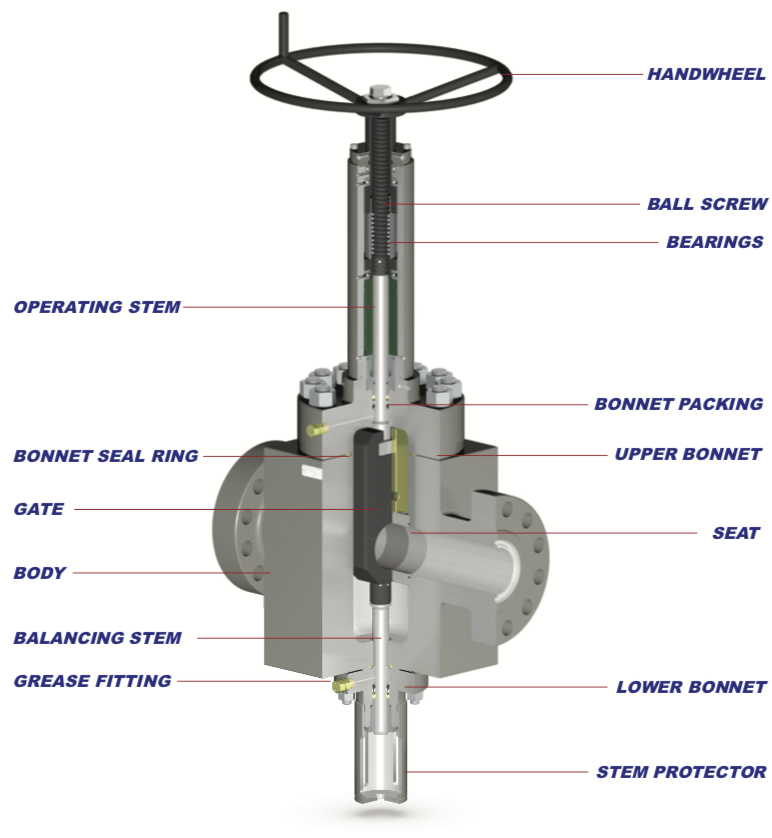
PRODUCT FEATURES
The following table outlines the key features of Valveworks USA FM Series Gate Valves, including Model FM1, Model FM2, and Model FM3. This comprehensive comparison highlights essential design elements such as bidirectional flow, available bore sizes, material classifications, gate types, sealing mechanisms, and temperature ratings. These industrial high-pressure gate valves are designed for maximum durability and reliability in oilfield and high-pressure applications.
| Key Features | Model FM1 | Model FM2 | Model FM3 |
|---|---|---|---|
| Flow Direction & Operation | Bidirectional | Bidirectional | Bidirectional |
| Available Bore Sizes & Rated Working Pressure (PSI) | 7-1/16” 10M, 7-1/16” 15M | 4-1/16” 15M | 5-1/8” 10M, 5-1/8” 15M |
| Pressure Specification Level (PSL) | PSL 1,2,3,3G,4 | PSL 1,2,3,3G,4 | PSL 1,2,3,3G,4 |
| Material Classifications | EE, FF, HH | EE, FF, HH | EE, FF, HH |
| Valve Body Construction | Forged Steel | Forged Steel | Forged Steel |
| Gate Type | Slab Gate | Slab Gate | Slab Gate |
| Sealing Mechanism | Pressure-Energized | Pressure-Energized | Pressure-Energized |
| Operation Type | Manual | Manual | Manual |
| Bore Type | Thru-Conduit | Thru-Conduit | Thru-Conduit |
| Gate/Seat Seal | Metal-to-Metal | Metal-to-Metal | Metal-to-Metal |
| Stem Design | Rising Stem | Rising Stem | Rising Stem |
| Stem Packing System | Opti-Seal Technology | Opti-Seal Technology | Opti-Seal Technology |
| Field Repacking Capability | Yes | Yes | Yes |
| Bearing Configuration | Triple Bearing System | Triple Bearing System | Triple Bearing System |
| Body Lubrication Fittings | 2 Lubrication Points | 2 Lubrication Points | 2 Lubrication Points |
| Body/Bonnet Connection | Bolted Assembly | Bolted Assembly | Bolted Assembly |
| Balance Stem Feature | Yes | Yes | Yes |
| End Connections | Flanged (RTJ) or Studded | Flanged (RTJ) | Flanged (RTJ) |
| Temperature Rating | -75°F (-60°C) to 250°F (121°C) | -75°F (-60°C) to 250°F (121°C) | -75°F (-60°C) to 250°F (121°C) |
a. Product Specification Level
b. Ball Screw Operated (BSOP) – Manual gate valve with torque reduction operator. See engineering note titled “Ball Screw Operated (BSOP)” for details.
c. Also referred to as “FULL OPENING”
d. Repacking is achieved via stem backseat method.
e. Ball screw housing equipped with grease port(s) and fitting(s) for bearing lubrication.
ENGINEERING NOTES
Pressure Testing – FM Series gate valves are not intended to be tested through the body lubrication fittings. These fittings are designed for lubrication purposes only. Shell tests and gate/seat tests shall be conducted from the end/outlet connection by qualified personnel only.
Ball Screw Operated (BSOP) – FM Series gate valves are offered with a ball screw operator, which greatly reduces the operating torque when opening and / or closing the valve.
TEMPERATURE RATING
The following table defines the temperature classifications for Valveworks USA gate valves, specifying the operating temperature ranges for each classification. These ratings ensure optimal performance in extreme cold and high-temperature industrial applications, making them ideal for oilfield and high-pressure environments.
| Temperature Classification | Operating Temperature Range (°F/°C) |
|---|---|
| K | -75°F (-60°C) to 180°F (82°C) |
| L | -50°F (-46°C) to 180°F (82°C) |
| N | -50°F (-46°C) to 140°F (60°C) |
| P | -20°F (-29°C) to 180°F (82°C) |
| S | 0°F (-18°C) to 140°F (60°C) |
| T | 0°F (-18°C) to 180°F (82°C) |
| U | 0°F (-18°C) to 250°F (121°C) |
| V | 35°F (2°C) to 250°F (121°C) |
MATERIAL REQUIREMENTS
The following table details the material class requirements for Valveworks USA gate valves, specifying the minimum material composition for body, bonnet, end connections, outlet connections, pressure-controlling parts, and stems. This classification ensures compliance with high-pressure industrial and oilfield standards.
| Material Class | Minimum Material Requirements | ||
|---|---|---|---|
| Body, Bonnet, End & Outlet Connections | Pressure-Controlling Parts & Stems | ||
| AA | General Service | Carbon or Low-Alloy Steel | Carbon or Low-Alloy Steel |
| BB | General Service | Carbon or Low-Alloy Steel | Stainless Steel |
| CC | General Service | Stainless Steel | Stainless Steel |
| DD | Sour Servicea | Carbon or Low-Alloy Steelb | Carbon or Low-Alloy Steelb |
| EE | Sour Servicea | Carbon or Low-Alloy Steelb | Stainless Steelb |
| FF | Sour Servicea | Stainless Steelb | Stainless Steelb |
| HH | Sour Servicea | Corrosion-Resistant Alloy (CRA)acd | Corrosion-Resistant Alloy (CRA)acd |
VALVEWORKS USA GATE VALVE MODEL EXPLANATION

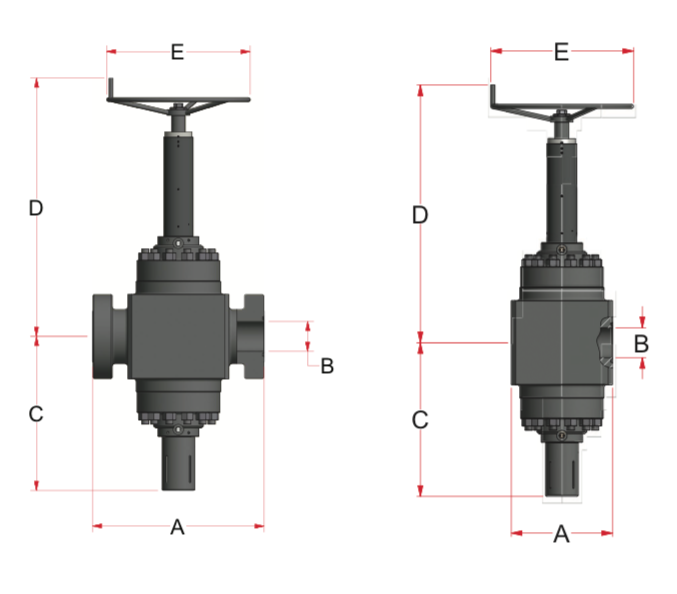
DIMENSION TABLE
FLANGED GATE VALVES
| SIZE | WP (PSI) | A | B | C | D | E | NT | RJ | BSS | WT (LBS) |
|---|---|---|---|---|---|---|---|---|---|---|
| 4-1/16" | 15K | 29" | 4-1/16" | 26" | 54-1/4" | 28" | 9 5/8 | BX-155 | 1" | 2050 |
| 5-1/8" | 10K | 29" | 5-1/18" | 26" | 52-1/8" | 28" | 11 3/4 | BX-169 | 1-3/8" | 1331 |
| 5-1/8" | 15K | 35" | 5-1/18" | 28-1/8" | 56-1/4" | 34" | 13 | BX-169 | 1-3/4" | 2331 |
| 7-1/16" | 10K | 35" | 7-1/16" | 36-1/2" | 61-1/4" | 34" | 17 3/4 | BX-156 | 1-3/4" | 4420 |
| 7-1/16" | 15K | 40-5/8" | 7-1/16" | 36-1/2" | 61-1/4" | 34" | 17 3/4 | BX-156 | 2" | 5410 |
STUDDED GATE VALVES
The following table outlines the dimensional specifications for Valveworks USA Studded Gate Valves. This chart includes critical data such as bore size, working pressure (WP PSI), end-to-end dimensions, and weight. Designed for high-pressure industrial and oilfield applications, these valves meet industry standards for performance and durability.
| Size | WP (PSI) | A | B | C | D | E | NT | RJ | BSS | WT (LBS) |
|---|---|---|---|---|---|---|---|---|---|---|
| 7 1/16 | 10K | 24 | 7 1/16 | 36 1/2 | 61 1/4 | 34 | 17 3/4 | BX-156 | 1 3/4 | 4630 |
| 7 1/16 | 15K | 24 | 7 1/16 | 36 1/2 | 61 1/4 | 34 | 17 3/4 | BX-156 | 2 | 4690 |
The following table provides a dimensional key for Valveworks USA FM Series Gate Valves, detailing critical measurements used in valve design and specification. These standardized dimensions ensure precise compatibility in industrial and oilfield applications.
| Key | Description |
|---|---|
| A | End to End Measurement |
| B | Valve Bore Size |
| C | Bore Centerline to Bottom of Valve |
| D | Bore Centerline to Top of Valve |
| E | Handwheel Diameter |
| NT | Number of Turns Required for Full Operation |
| RJ | Ring Joint Type for Flange Connections |
| BSS | Bonnet Stud Size |
| WT | Approximate Valve Weight (lbs) |
ABBREVIATION KEY
- BSOP = BALL-SCREW OPERATED
- SG = SLAB GATE
- FE = FLANGED END
- STD =STUDDED END
- RTJ = RING TYPE JOINT
- D/O = DIRECT OPERATING
- R/A = REVERSE ACTING
- KU = TEMP. CLASS K/U (-75°F TO 250°F)
- LU = TEMP. CLASS L/U (-50°F TO 250°F)
- PU = TEMP. CLASS P/U (-20°F TO 250°F)
- PSL = PRODUCT SPECIFICATION LEVEL
- PR = PERFORMANCE REQUIREMENT
- CRA = CORROSION-RESISTANT ALLOY
- HF = HARDFACED TUGSTEN CARBIDE